CHANCE Helical Piering System
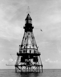 The earliest known use of an anchor foundation was for the support of lighthouses in tidal basins around England. A blind English brickmaker, Alexander Mitchell, is credited with the design of a “screw pile” for this purpose in 1833. The use of the “screw pile” was apparently successful, but advancement of the helix-plate foundation did not progress.
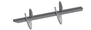
In the 1950s, the A.B. Chance Company introduced the Power-Installed Screw Anchor (PISA®) for resisting tension loads. The anchor consists of a plate or plates, formed into the shape of a helix or one pitch of a screw thread. The plate is attached to the central shaft. The helix plate has its characteristic shape to facilitate installation. Installation is accomplished by applying torque to the anchor and screwing it into the soil. The effort to install the anchor is supplied by a torque motor.
With the development of the tension screw anchor, came the use of the same or similar devices to resist compression loads. Thus, screw pile foundations came into greater use. Various sizes and number of helices have been used with shafts of varying sections to provide foundations for different applications. In the past 40 years, projects that have utilized screw pile foundations include electric utility transmission structures, Federal Aviation Administration flight guidance structures, pipeline supports, building foundations, remedial underpinning, streetlights, walkways in environmentally sensitive areas and many others.
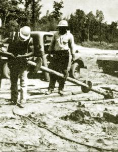
The screw pile foundation system is known for its ease and speed of installation. Installation generally requires no removal of soil, so there are no spoils to dispose of. Installation causes displacement of soils for the most part. However, in the case of a foudnation with a pipe shaft, some soil will enter the interior of the pipe until it becomes plugged. Installation equipment can be mounted on vehicles when required. The installation of a screw pile for practical purposes is vibration free. These features make the screw pile foundation attractive on sites that are environmentally sensitive. Installations near existing foundations or footings generally cause no problems. However, the screw pile foundation generally cannot be installed into compentent rock or concrete. Penetration will cease when materials of this nature are encountered.
How it Works
The bearing calculations are suitable for both compression and tension as long as the soils being loaded are considered.
Foundation design typically occurs in two steps:
Select the anchor-helix configuration based on soil characteristics and load required. Select shaft configuration based on load and anticipated installation torque.
Capacity Equation
The design procedures utilized by A.B. Chance is based upon the accepted General Bearing Capacity Equation:
A = (C)(Nc) (B)(Nq) where
A = ultimate soil bearing pressure
C = cohesion of soil
B = overburden pressure
Nc and Nq are bearing capacity factors for local soil shear conditions
The load capacity of a multi-helix anchor is the sum of all individual helix capacities. Individual helix bearing capacity is the product of its projected area (Ah) and the bearing pressure (A). Reduction in load capacity should be accounted for in sensitive soils. Allowances should be made when the zone of influence for a helix includes strata of different strengths.
This analysis depends on a “deep anchorage” failure mode. This condition is satisfied when the helix depth-to-diameter ratio is a minimum of 5.
Holding Strength Related to Installing Torque
Monitoring installation torque helps indicate anchor capacity. The ratio between holding capacity and installation torque suggests 10 as a rule of thumb. This value typically ranges from 7 to 12. Torque monitors are available from Chance and Helical Concepts. Their use provides a good method of quality control during installation.
For more information, please visit our Technical Page.